Table of Contents
- Product Instructions for Use 1
- Pre-commissioning Preparations 2
2.1 Software Installation 2
2.2 Firmware Installation 4
2.3 Login 5
2.4 Version Upgrade 6 - Receiver Settings 8
3.1 Signal Icon Definitions 8
3.2 Network Base Station 9
3.2.1 One-Click Fix 9
3.2.2 Multi-Network Mode 10
3.3 Radio Base Station 11 - Mechanical Calibration 13
4.0 Information Entry 13
4.1 Baud Rate Setting 14
4.2 Installation Entry 15
4.3 Angle Sensor Calibration 17
4.4 Steering Actuator Calibration 17
4.5 Installation Error Calibration 18 - Data Backup and Restoration 21
5.1 Backup 21
5.1.1 Manual Backup 21
5.1.2 Historical Backup 21
5.1.3 Network Backup 22
5.2 Restoration 23 - Implement Settings 24
- Navigation Lines 25
7.1 Quick Line Setting 25
7.2 Standard Line Setting 25 - Other Functions 27
8.1 Remote Assistance 27
8.2 Quick Parameter Check 27
8.3 Track Function 28
8.3.1 On/Off Mode 28
8.3.2 Auto/Manual Mode 29
8.4 Work Report and Operating Area 29
8.5 Navigation Line Sharing 30
8.5.1 Navigation Line Sharing via Identification Code 30
8.5.2 USB Import and Export 31
8.6 Multi-Language Display 31 - Troubleshooting of Common Issues 32
9.1 Fault Diagnosis 32
9.2 Heading Reversal 33
9.3 Line Zeroing 34
9.4 Straightness Issues 35
9.4.1 Quick Parameter Adjustment 35
9.4.2 Scenario Switching 36
9.5 Headland Turning Adjustment 37
9.5.1 Quick Adjustment Method 37
9.5.2 Standard Adjustment Method 38
1. Product Instructions for Use
- When the assisted driving or autopilot function is activated, the driver shall continuously observe obstacles ahead and assess potential hazards.
- It is strictly prohibited to power on the assisted driving or autopilot system outside of designated agricultural machinery operation areas.
- Fatigued driving is strictly prohibited.
- It is strictly prohibited to get on or off the vehicle during assisted driving or autopilot operation.
- Unauthorized disassembly and assembly of equipment is strictly prohibited. Hardware malfunctions or damage caused by human factors are not covered under the warranty.
2. Pre-commissioning Preparations
2.1 Software Installation
Note: New equipment generally comes with pre-installed software from the factory, eliminating the need for manual installation. You can proceed directly to subsequent steps.
a. Insert the USB drive into the display. Tap 【】 and then 【ES File Explorer】 sequentially.
b. Locate the USB drive path on the left panel of ES File Explorer (usually named USB500*). Find the software installation package in the USB drive, which is generally named [AgNav-3._LOVOL-.apk]. Tap the installation package and then select 【Install】.
c. Once the software installation is complete and a confirmation prompt appears, tap 【Open】 to launch the software interface. The software installation is now finished.
2.2 Firmware Installation
Note: New equipment generally comes with a factory-installed firmware version compatible with the software, so no manual installation is required. You can proceed directly to subsequent steps.
a. Connect your Android phone or computer to the controller's Wi-Fi. The Wi-Fi name is GNSS-[SN Number] (the SN number is the controller's factory serial number, which can be found on the controller nameplate). The password is 12345678.
b. Open your browser and enter the URL 【192.168.1.1】.
d. After entering the interface, tap 【Firmware】 > 【Firmware Upgrade】 > 【Select File】 in sequence. Choose the corresponding firmware file and click 【Upload】. Upon successful upload, the LEDs on the controller will flash sequentially, indicating that the controller is undergoing automatic upgrading. Do NOT turn off the controller during this process, as it may cause system crash of the controller. The upgrade takes approximately 3-5 minutes, after which the controller will restart automatically, and the firmware upgrade will be completed.
Important Note: The device must NOT be powered off during firmware upgrading!
Tips: The path of files received via WeChat on an Android phone is [Phone Storage] > [Android] > [data] > [com.tencent.mm] > [MicroMsg] > [Download].
Common Issues:
① If the webpage fails to display or shows abnormalities after opening, ensure the correct URL for the corresponding version is entered, then try clearing the browser cache or switching to another browser. Recommended browsers include UC Browser, Google Chrome, Mozilla Firefox, and 360 Browser.
② If there is no response after clicking 【Upload】 or a "file selection error" prompt appears, check if the firmware file name is correct. The firmware name must not be modified in any way, and no spaces or numeric identifiers (e.g., (1)) should be added.
2.3 Login
A user agreement will pop up when the software is launched. Read and accept the user agreement, then tap 【Agree】 to enter the navigation main interface.
Devices that have not been logged in with a mobile phone number will automatically enter the navigation main interface in Guest Mode.
- Technical personnel performing commissioning may tap 【Cancel】 to proceed with operations.
- End users must tap 【Go to Login】 and log in using their mobile phone number + verification code. Note: The 【Get Verification Code】 function requires the tablet to be connected to a network.
2.4 Version Upgrade
After launching the software, if the software and firmware versions are incompatible, a prompt box will appear. Tap 【Upgrade】 to directly access the About interface (this interface can also be accessed via 【】 > 【About】), where you can check the current software version and firmware version. If the current version is not the recommended one, tap 【Upgrade】 > 【System Update】 in sequence, then click 【Confirm】 in the pop-up dialog box to start the system update process.
The system update typically takes around 10 minutes. Do NOT perform any operations during this period. After the update is complete, a software installation dialog box will pop up. Follow the same steps as installing software packages on Android systems.
Notes:① System update requires both the display and the controller to be connected to a network. If the display has no network access, the software cannot be updated automatically; if the controller has no network access, the firmware cannot be updated automatically.② Once the system update starts, it cannot be terminated midway except by force-closing the software or waiting for the update to complete.③ Do NOT power off the controller during firmware upgrading (when the LEDs on the controller are flashing sequentially), as this may render the controller inoperable ("bricked").
The upgrade interface also supports separate software upgrade and firmware upgrade, with the same operation methods and requirements as the 【System Update】 function. Other upgrade functions in this interface are generally not required for use.
3. Receiver Settings
3.1 Signal Icon Definitions
The three signal icons in the upper left corner of the software interface indicate signal status. As shown in the figure below, if all three boxes in the upper left corner display white text on a black background, the RTK signal is currently in normal status.
If the signal is normal, no base station settings are required. Proceed directly to Section 4.
Signal Details:
- Box A: Number of satellites / RTK status (Normal status: 4 = RTK Fixed, 1 = Single Point, 2 = DGPS, 5 = RTK Float).
- Box B: Differential age (i.e., signal delay, the time elapsed since the last valid base station signal was received) / Base station mode (NET = Network Base Station; a numeric value indicates the channel used by the Radio Base Station).
- Box C: Positioning accuracy error. As long as it is not displayed in red, it meets the requirements for autopilot operation.
The controller is equipped with an LED indicator set, with different LEDs representing different meanings:
- Red LED: Differential status indicator. Solid red light indicates normal RTK status, and the device is ready for use.
- Blue LED: Satellite searching indicator. It flashes N times, pauses for 5 seconds, and then starts a new cycle of flashing. N represents the current number of satellites being tracked.
- Green LED: Base station signal indicator. It flashes once each time a base station signal is received. Under good signal conditions, it flashes approximately once per second.
3.2 Network Base Station
To use the Network Base Station, ensure the device is connected to a network and that base station signals are available in the surrounding area.
The controller has a built-in eSIM card. New devices generally come with a pre-installed SIM card from the factory, which is a data-limited card that supports the normal operation of navigation functions. For non-standard usage requirements, the SIM card inside the device can be replaced by the user.
When logging in to the Network Base Station, the system simultaneously connects to three signal channels to obtain base station data, maintaining continuous signal connectivity. If a signal is interrupted midway, the system will automatically redial and reconnect. During operation, the system automatically selects and uses the channel with the strongest signal. Therefore, to maintain normal operation of the Network Base Station mode, it is only necessary to ensure that at least one signal channel is properly connected to both the controller and the display.
3.2.1 One-Click Fix
The One-Click Fix function does not require inputting any base station information; it receives signals from the SWAS network base station in a targeted manner. Using One-Click Fix requires background registration. If login fails despite confirming that the device is within the base station signal coverage area and the network connection is normal, it indicates that the device has not been registered in the background. Contact technical support personnel for resolution. The operation method for One-Click Fix is as follows:
a. Tap the signal box in the upper left corner to enter the Differential Settings interface.
b. Set the working mode to 【One-Click Fix (VRS)】 or 【One-Click Fix (Single Base Station)】, then wait for the system to log in automatically. The function can be used normally as long as any one channel shows "Login Successful" and flashes. It is recommended to prioritize the 【One-Click Fix (VRS)】 mode.
3.2.2 Multi-Network Mode
The Multi-Network Mode supports logging in to any network base station that complies with the CORS protocol. The operation method is as follows:
a. Tap the signal box in the upper left corner to enter the Differential Settings interface.
b. Set the working mode to 【Multi-Network Mode】 and tap 【Add】.
c. Enter the base station information and tap 【Save】. Contact technical personnel to obtain base station information for different regions.
d. Select the base station and tap 【Apply】.
3.3 Radio Base Station
The controller incorporates a radio module, which supports multiple protocols including Default, Transparent, and TT450S. The following are the software settings for the standard matching base station (this manual does not include the base station-side setup procedures):
a. Tap the signal box in the upper left corner to enter the Differential Settings interface.
b. Set the working mode to 【Built-in Radio】. Adjust the base station channel to match that of the base station. Keep other parameters at their default values (Radio Protocol: 【Default】, Radio Step Value: 【25】, Air Baud Rate: 【9600】, Radio Power: 【0.5W】). Tap 【Apply】 and return to the previous interface.
Note: For special frequency usage, set the channel to 【0】 and manually input the frequency.
4. Mechanical Calibration
4.0 Information Entry
On the navigation main interface, tap 【】 > 【192.168.1.1】 > 【WEICHAI LOVOL P7000 Navigation Agricultural Machinery Autopilot】 > 【35000】 > 【P7000】 sequentially. In the information entry interface, fill in 【35000】 for the organization code and select 【P7000】 for the vehicle model. Filling in other information is optional. After completing the entry, ensure the display is connected to the network and tap 【Register】.
To modify the data previously entered in the information entry interface, enter the installation entry interface and tap the 【】 icon in the upper right corner to re-access the information entry interface.
4.1 Baud Rate Setting
a. On the mechanical calibration interface, tap 【Advanced】, select 【Ag_NX01_default】, click 【Modify】, enter the password 【012】, and access the settings interface.
b. Set 【Steering Sensitivity】 to 【250】 and tap 【Confirm】.
c. Tap 【Apply】.
d. Restart the entire set of navigation and autopilot equipment. The configured communication baud rate will take effect after the device restarts.
4.2 Installation Entry
On the main interface, tap 【】 > 【Mechanical Calibration】 sequentially. The system will automatically enter the installation entry interface.
a. Installation Information
- Vehicle Type: Select 【Front Wheel Steering】 by default; no modification is required.
- Actuator Type: Select 【Solenoid Valve】.
- Angle Sensor Type: Select 【Mechanical Angle Sensor】.
After completing the settings, tap 【Next Step】.
b. Dimension Information
- Wheelbase (A): Horizontal distance between the centers of the front and rear axles.
- Rear Axle to Mounting Point Distance (B): Default value 【0】.
- Rear Axle Height (F): Vertical distance from the center of the rear axle to the ground.
- Front Wheel Track (G): Horizontal distance between the centers of the two front wheels.
- Antenna to Centerline Distance (C): Default value 【0】 when the controller is mounted on the vehicle's centerline.
- Antenna Position Relative to Centerline: The 【Left】 and 【Right】 options are invalid when the Antenna to Centerline Distance is 0.
- Antenna to Rear Axle Distance (D): Horizontal distance from the controller's blue LED to the center of the rear axle.
- Antenna Position Relative to Rear Axle: Relative position between the controller's blue LED and the center of the rear axle, determined based on the vehicle's forward direction. Select 【Front】 if the controller's blue LED is positioned forward; select 【Rear】 if it is positioned backward.
- Receiver Height (E): Vertical distance from the controller's blue LED to the ground.
After entering the data, tap 【Next Step】.
4.3 Angle Sensor Calibration
After completing the installation entry, the system will automatically enter the angle sensor calibration interface. Select 【Manual】 mode in the upper right corner of the interface and tap 【Complete】. There is no need to modify any parameters in the interface.
4.4 Steering Actuator Calibration
After the angle sensor calibration is completed, the system will automatically enter the actuator calibration interface. Select 【Manual】 mode in the upper right corner of the interface and tap 【Complete】. There is no need to modify any parameters in the interface.
4.5 Installation Error Calibration
The installation error calibration requires a 3-5 hectare field with a straight path of at least 50 meters, which is sufficient for the vehicle to make a U-turn. The specific operation steps are as follows:
① Tap 【】 > 【Mechanical Calibration】 > 【Installation Error Calibration】 sequentially, then click 【Enter Calibration Wizard】.
② Park the vehicle in a suitable position, tap 【Start】. The system will automatically generate a straight line "A+" and enter the "Autopilot" state.
③ Drive forward at a speed of approximately 2 km/h for more than 30 meters, stop the vehicle, and tap 【Next Step】. The system will switch to "Manual Driving" state.
④ Drive forward manually for at least 10 meters (drive as far as possible if the field size permits), make a U-turn, and return to the same navigation line. When the distance from the starting point exceeds 40 meters, tap 【Next Step】. The system will enter the autopilot state (try to stay close to the navigation line; manual steering adjustments can be made to align with the line).
⑤ Autonomously drive back to within 1 meter of the starting point and tap 【End】. The installation error calibration is now complete.
⑥ The system will display the calibration status in a dialog box. If the calibration is successful, tap 【Complete】. The system will then revert to manual driving mode.
Upon successful completion of the installation error calibration, all device calibration tasks are finished.
5. Data Backup and Restoration
5.1 Backup
The system supports three backup methods: manual backup, historical backup, and network backup. To access the backup and restoration interface, tap 【】 > 【System Settings】 > 【Backup and Restoration Settings】 sequentially on the navigation main interface.
Important Note: After device commissioning is completed, technical personnel MUST perform a manual backup following the method described in 5.1.1.
Backup files are divided into two categories: "Calibration and Configuration Parameters" and "Farm Navigation Line Data".
- "Calibration and Configuration Parameters" include parameters from receiver settings, mechanical calibration, implement settings, and system settings.
- "Farm Navigation Line Data" include data for farms, fields, tasks, boundaries, and navigation lines.
5.1.1 Manual Backup
To perform a manual backup, access the backup and restoration interface and tap 【Backup】. A "Backup Successful" prompt indicates the completion of the backup operation. Re-enter the backup and restoration interface to view the backup file. Manual backup simultaneously saves both "Calibration and Configuration Parameters" and "Farm Navigation Line Data".
Manual backup files are stored in the display and only one copy is retained. New manual backups will overwrite previous files. Manual backup files should be created after successful commissioning and should not be overwritten unless a new calibration is performed.
5.1.2 Historical Backup
Historical backups are automatically saved when the system has been running for more than 5 hours, with a maximum of one backup per day. Historical backups simultaneously save both "Calibration and Configuration Parameters" and "Farm Navigation Line Data".
Historical backup files are stored in the display, with a maximum of 30 files retained. The 31st file will overwrite the 1st file, and so on. During restoration, you can select files from specific dates and restore either "Calibration and Configuration Parameters" or "Farm Navigation Line Data" individually.
5.1.3 Network Backup
The system automatically uploads configuration files to the server for network backup each time parameters are modified, with a maximum of one backup per day. Network backup only saves "Calibration and Configuration Parameters".
Network backup requires the display to be connected to a network. Files are stored on the server, with a maximum of 3 files retained. Network backup uses the controller's SN number as the identification code. This means the network restoration function can still be used if the display is replaced but the controller remains unchanged.
During restoration, you can select files from specific dates and only restore "Calibration and Configuration Parameters".
5.2 Restoration
If the equipment malfunctions due to improper parameter modification or major component replacement during operation, the parameter restoration function can be used.
To access the backup and restoration interface, tap 【】 > 【System Settings】 > 【Backup and Restoration Settings】 sequentially on the main interface. Select the backup data source, find the corresponding backup file by date, and tap 【Restore】 to revert the system parameters to the state saved in the selected backup file.
6. Implement Settings
On the main interface, tap 【Menu】 > 【Implement】 > 【Working Width】 sequentially to modify implement settings.
- Implement Width: The actual effective working width of the implement. For example, for a seeder, it refers to the horizontal distance from the leftmost seed metering unit to the rightmost seed metering unit.
- Row Spacing: The distance that needs to be left outside the effective coverage area of the implement during round-trip operations. For example, for a seeder, it refers to the spacing required between adjacent rows during round-trip operations.
- Axle to Plow Distance: Enter 0 by default; no modification is required.
- Center Offset: The distance by which the implement is offset from the vehicle's centerline when mounted. A negative value indicates a left offset, and a positive value indicates a right offset. Enter 0 if the implement is mounted centrally.
7. Navigation Lines
The system supports 10 line-setting methods. Commonly used straight and curved line types can be set using the Quick Line Setting function on the main interface, while other types of navigation lines require the Standard Line Setting function in the navigation line interface.
7.1 Quick Line Setting
On the navigation main interface, tap 【Line Setting】 to open the Quick Line Setting dialog box, and the letter 【A】 will appear in the lower right corner. Tapping 【A】 directly without opening the dialog box will create a straight line by default.
To modify the navigation line name or type, make changes in the dialog box.
7.2 Standard Line Setting
On the main interface, tap 【】 > 【Navigation Lines】 sequentially to access the navigation line management interface, which displays all previously set navigation lines.
In the navigation line management interface, tap 【Add】 to select different types of navigation lines. After selecting the type and modifying the navigation line name, tap 【Create】. Descriptions of various navigation line types are as follows:
- AB Line: Two-point line setting. An infinitely extended straight line formed by connecting points A and B.
- A+ Line: An infinitely extended straight line with the origin at the center of the vehicle's two rear wheels and the direction aligned with the vehicle's forward heading (line setting must be performed when the device's heading is normal).
- Curved Border Plowing Line: After defining the field boundary, the system automatically plans curved lines suitable for plowing. During autopilot along plowing lines, the system will automatically make U-turns at field ends. Suitable for standard rectangular fields; generally not recommended.
- Irregular Border Plowing Line: After defining the field boundary, the system automatically plans curved lines suitable for plowing. During autopilot along plowing lines, the system will automatically make U-turns at field ends. Suitable for irregularly shaped fields; planning may fail for extremely irregular fields.
- Circular Curve (Single-Point Type): An infinite number of circular navigation lines with the origin at the center of the vehicle's two rear wheels and spaced at intervals equal to the working width (implement width + row spacing).
- Circular Curve (Three-Point Type): A circle planned by three points A, B, and C.
- 90° Line: A line formed by reversing an existing AB line by 90 degrees.
- Parallel Curve: A curve formed by recording the driving trajectory between points A and B and replicating it in a direction perpendicular to the line connecting A and B.
- Translational Curve: A curve formed by recording the driving trajectory between points A and B and translating it orthogonally.
- Improved Translational Curve: A smoothed version of the translational curve, more suitable for high-speed curved path operations.

8. Other Functions
8.1 Remote Assistance
On the main interface, tap 【Menu】 > 【Help】 > 【One-Click Help】 sequentially to launch the remote assistance software (if opening it for the first time, follow the software prompts to upgrade and install, then restart the software). Technical personnel can remotely control the device by entering the machine's identification code via the control terminal software to resolve issues quickly.
8.2 Quick Parameter Check
To facilitate quick troubleshooting during navigation, tap 【Menu】 > 【Help】 > 【Parameter Check】 sequentially on the main interface to view commonly used data rapidly.
8.3 Track Function
The navigation device supports two track display modes, which can be modified in the Track Switch Settings under 【】 > 【System Settings】 > 【Basic Settings】 on the main interface.
8.3.1 On/Off Mode
In On/Off mode, there is a 【Track】 button in the menu bar. When the track function is enabled, the vehicle will continuously record the driving track during movement; when disabled, no track will be recorded. This mode is independent of the auto/manual driving status.

8.3.2 Auto/Manual Mode
In Auto/Manual mode, there is no 【Track】 button on the main interface. The vehicle records the driving track only when in autopilot mode; no track is recorded when moving in manual driving mode.

8.4 Work Report and Operating Area
The upper right corner of the main interface displays the autopilot area of the current task. Tapping this area will show the complete work report.
Tapping the area display icon in the upper right corner will access the work report interface, which displays:
- Boundary Area (available only if the field boundary has been defined).
- Track Area (the area covered by the track in On/Off mode or Auto/Manual mode).
- Autopilot Distance.
- Autopilot Area.
Calculation Formula: Autopilot Area = Autopilot Distance × (Implement Width + Row Spacing).
The area of overlapping operation regions within the same task will be automatically deduplicated. However, if the device is restarted and operations are performed in the same area as before the restart, the overlapping area will not be deduplicated.
Important Note: Using the Quick Line Setting function on the main interface will automatically create a new task, and all data in the work report will be reset to zero. Previous data can be viewed in 【】 > 【Farm Management】 > 【Task Management】.
8.5 Navigation Line Sharing
8.5.1 Navigation Line Sharing via Identification Code
On the main interface, tap 【】 > 【Navigation Lines】 sequentially to access the navigation line interface. Navigation lines can be shared when the display is connected to a network. In the navigation line interface, select the navigation line to be shared (only AB lines are supported for sharing), tap the three-dot icon in the upper right corner, then select 【Export】 > 【Share】. The system will generate an identification code.
On another device, access the navigation line interface, tap the three-dot icon in the upper right corner, select 【Import】 > 【Get Shared Line】, and enter the identification code to download the navigation line shared by the other vehicle.
Note: Navigation lines output by the beacon via sharing codes can also be received using the 【Get Shared Line】 function.

8.5.2 USB Import and Export
In the navigation line interface, tap the three-dot icon in the upper right corner, then select 【Export】 > 【Export】 to export the navigation line file. The file will be saved in the directory [Main Directory] > [NAV] > [AgNav3.0] > [Export] > [NavLine-Export]. You can copy the file to a USB drive and transfer it to another display. To import a navigation line, access the navigation line interface, tap the three-dot icon in the upper right corner, select 【Import】 > 【Local Import】, and choose the corresponding navigation line file.
8.6 Multi-Language Display
The system supports three display languages: Chinese, English, and Russian. The language can be switched in 【】 > 【System Settings】 > 【Basic Settings】. The language change will take effect after restarting the software.
Note: Do NOT modify the language in the display's native settings. The tablet's system language and the software language can be different.
Common Issue: If some text entries are truncated after switching languages, the entry will be marked with 【…】. Tapping the entry will scroll the text for full display (text on button icons will not scroll).
9. Troubleshooting of Common Issues
9.1 Fault Diagnosis
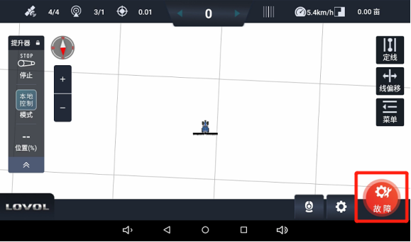
Any fault that prevents normal autopilot operation will be displayed in the lower right corner of the main interface. Tapping 【Fault】 will access the diagnosis interface. In this interface, tapping the fault item will display fault analysis and troubleshooting solutions. Follow the provided solutions to resolve the issue.
9.2 Heading Reversal
In rare cases, the device may experience heading errors after startup, where the system displays a "Reversing" prompt when the vehicle is moving forward. Autopilot operation in this state will result in poor straightness performance. If the heading is confirmed to be reversed, tap 【Menu】 > 【Help】 > 【Reverse Heading】 sequentially on the main interface to resolve the issue.
Note: The Heading Reversal function must be used in manual driving mode.
9.3 Line Zeroing
The Line Zeroing function can be used when you want the planned navigation line for the adjacent field to be exactly the same as the previous navigation line after completing autopilot operations in one field.

Manually drive the vehicle to a suitable position, ensuring the vehicle's heading is roughly aligned with the direction of the existing navigation line. Tap 【Line Offset】 > 【Zero】 sequentially to move the navigation line to the current vehicle position.
- Before Line Zeroing
- After Line Zeroing
9.4 Straightness Issues
Common tractors and transplanters are front-wheel steering models. This manual only provides instructions for front-wheel steering vehicles. For adjustment methods for rear-wheel steering, articulated, and crawler-type models, refer to the technical bulletin.
9.4.1 Quick Parameter Adjustment
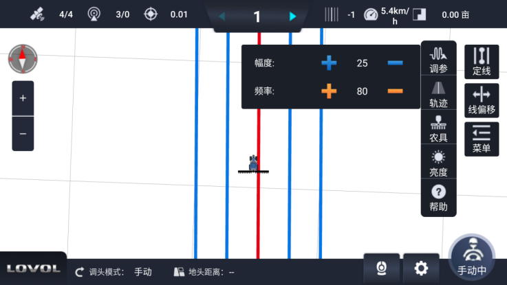
There is an 【Adjust Parameters】 button in the 【Menu】 on the main interface. Tapping this button allows you to adjust the values of 【Amplitude】 and 【Frequency】 using the plus and minus buttons.
- Amplitude: The adjustment range of the steering wheel. Default value: 25. A larger value results in a greater steering wheel adjustment range.
- Frequency: The adjustment speed of the steering wheel. Default value: 80. A larger value results in a faster steering wheel adjustment speed.
9.4.2 Scenario Switching
On the main interface, tap 【】 > 【Mechanical Calibration】 > 【Advanced】 sequentially to access the advanced parameter interface. This interface includes two sets of scenario parameters: NX64 and NX01. It is recommended to use the default NX01 scenario parameters first. If the straightness performance is poor, and it has been confirmed that the vehicle is functioning properly and the equipment has been installed and calibrated according to requirements, you can modify and switch the scenario type.
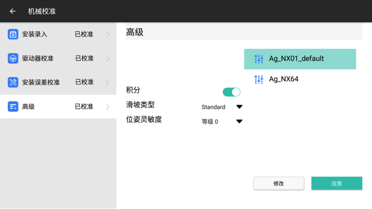
- Scenario NX01: Supports both straight and curved path modes. This is the default scenario with relatively gentle control, and it has better adaptability to high-speed operation compared to Scenario 64.
- Scenario 64: Supports both straight and curved path modes with more aggressive control.
9.5 Headland Turning Adjustment
If headland turning issues occur (i.e., inconsistent headland turning sizes, with adjacent turns consistently being one large and one small) after the navigation equipment has been installed and calibrated according to requirements, this phenomenon is caused by the implement being mounted off-center. The fundamental solution is to adjust the implement's mounting position to align it with the vehicle's centerline. If on-site conditions prevent such adjustments, the headland turning adjustment function in the software can be used.
Note: When measuring headland turning sizes, avoid areas within 20 meters of field ends and sections with obvious curves.
9.5.1 Quick Adjustment Method
The Quick Adjustment Method requires the total working width (implement width + row spacing) to be set correctly. Refer to Chapter 6: Implement Settings for implement configuration methods. Do NOT use this method if the actual working width of the implement has not been measured!
To quickly adjust headland turning, tap 【Menu】 > 【Implement】 > 【Headland Turning】 sequentially on the main interface. A headland turning adjustment dialog box will appear.
Tap the arrow corresponding to the desired direction of vehicle movement, adjust the distance accordingly, and tap 【Confirm】. Each tap of the arrow adjusts the distance by 1 cm. After adjustment using the Quick Adjustment Method, no further adjustments are required unless the implement is disassembled or moved.
Example: If the left headland turning is 10 cm too large and you want the vehicle to move left, tap the 【←】 arrow 10 times and then click 【Confirm】.
9.5.2 Standard Adjustment Method
To use the Standard Adjustment Method, ensure the implement settings are configured strictly in accordance with Chapter 6: Implement Settings. Drive autonomously for three rows and measure the two headland turning sizes. On the main interface, tap 【Menu】 > 【Implement】 > 【Working Width】 > 【Auto Calculate Headland Turning】 sequentially to access the automatic headland turning calculation interface.
Select the scenario diagram corresponding to the three rows driven autonomously, enter the two headland turning data values (S1/S2, in meters), and tap 【Complete】. The system will automatically calculate the headland turning parameters and modify the values of 【Implement Width】 and 【Center Offset】.